Engineering
“Engineering is the closest thing to magic that exists in the world.” - Elon Musk
Engineering Projects
Here are some engineering projects. To see more of my projects/classwork check out my GrabCAD and Github
Bradley University Senior Design: Drop Tower
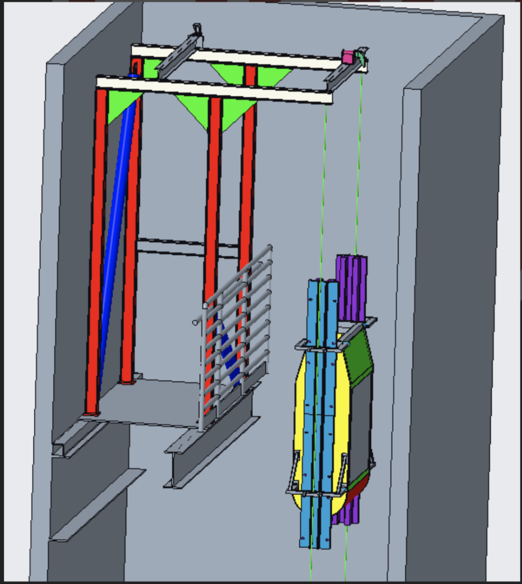
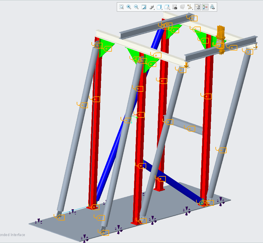
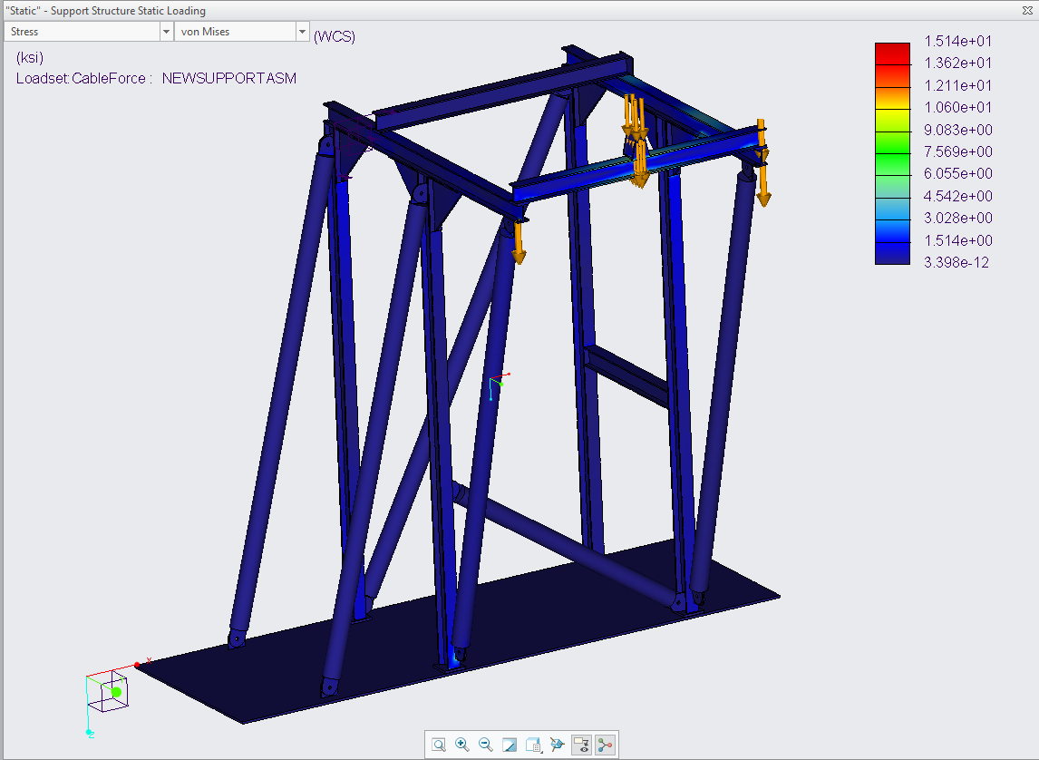
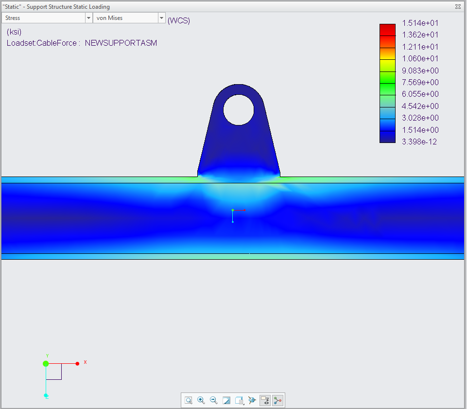
Bradley had placed a drop tower into the Business Engineering Convergence Center but had no real plans for it. My team, composed of five total members, was delegated with the task of making the Bradley University drop tower useable. The team ended up creating a support structure for a dropping test section. The support structure would be placed on the fifth story of the building. This test section would perform microgravity experiments. I ran the FEA for our team. Images of the final analysis can be seen down below. The first image shows the setup; the second illustrates the structure after the FEA was performed. The last image shows the zoomed-in section of the cross beam. This project gave me a lot of experience running static and modal FEA.
Tennis Robot
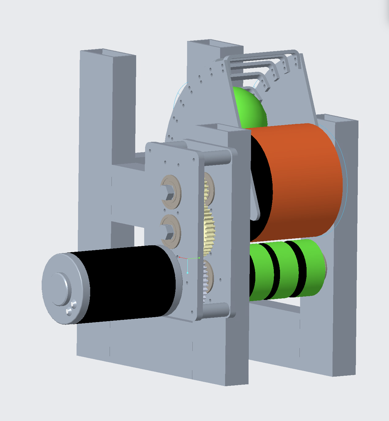
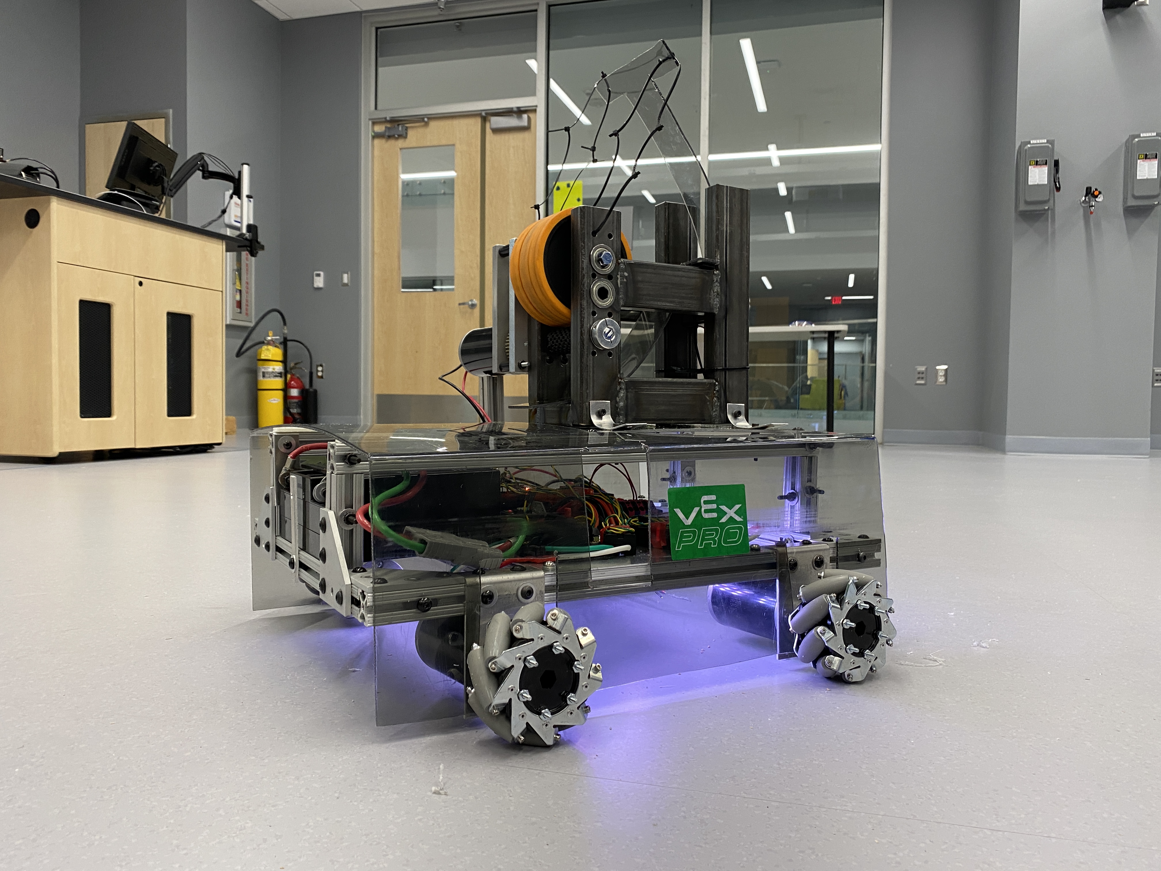
In high school, I participated in FRC robotics. FRC robotics is what made me find my passion for engineering and choose my career path. The mechanical engineering curriculum did not offer much hands on experience. My university offered a special projects course as an elective. I decided to create a course and create a robot. I recruited eight other people to join me and a create a robot in the Spring Semester of 2021. This class demanded that we used previous knowledge from courses that we had taken. Some of these courses included computer-aided design, electrical engineering, machine design, and machine kinematics, and computational methods (Matlab). This project did not turn out the way I expected, but was still really fun. I used Creo extensively. Some of the CAD work and images can be seen down below.

End Effector Robot
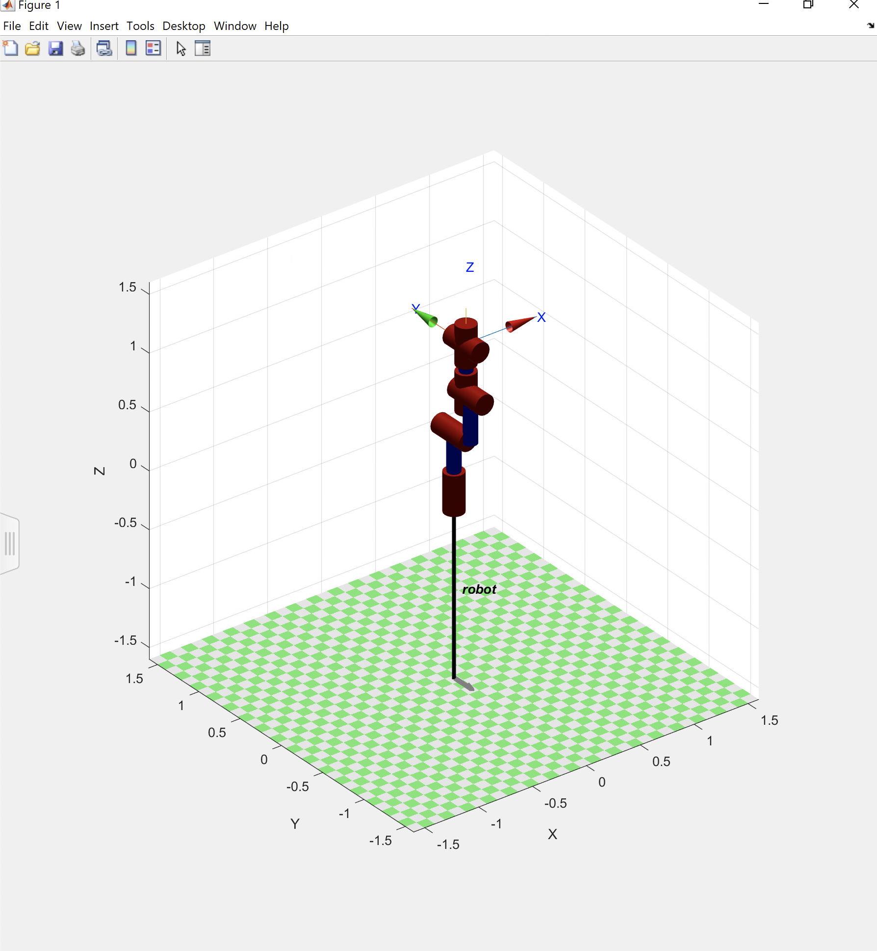
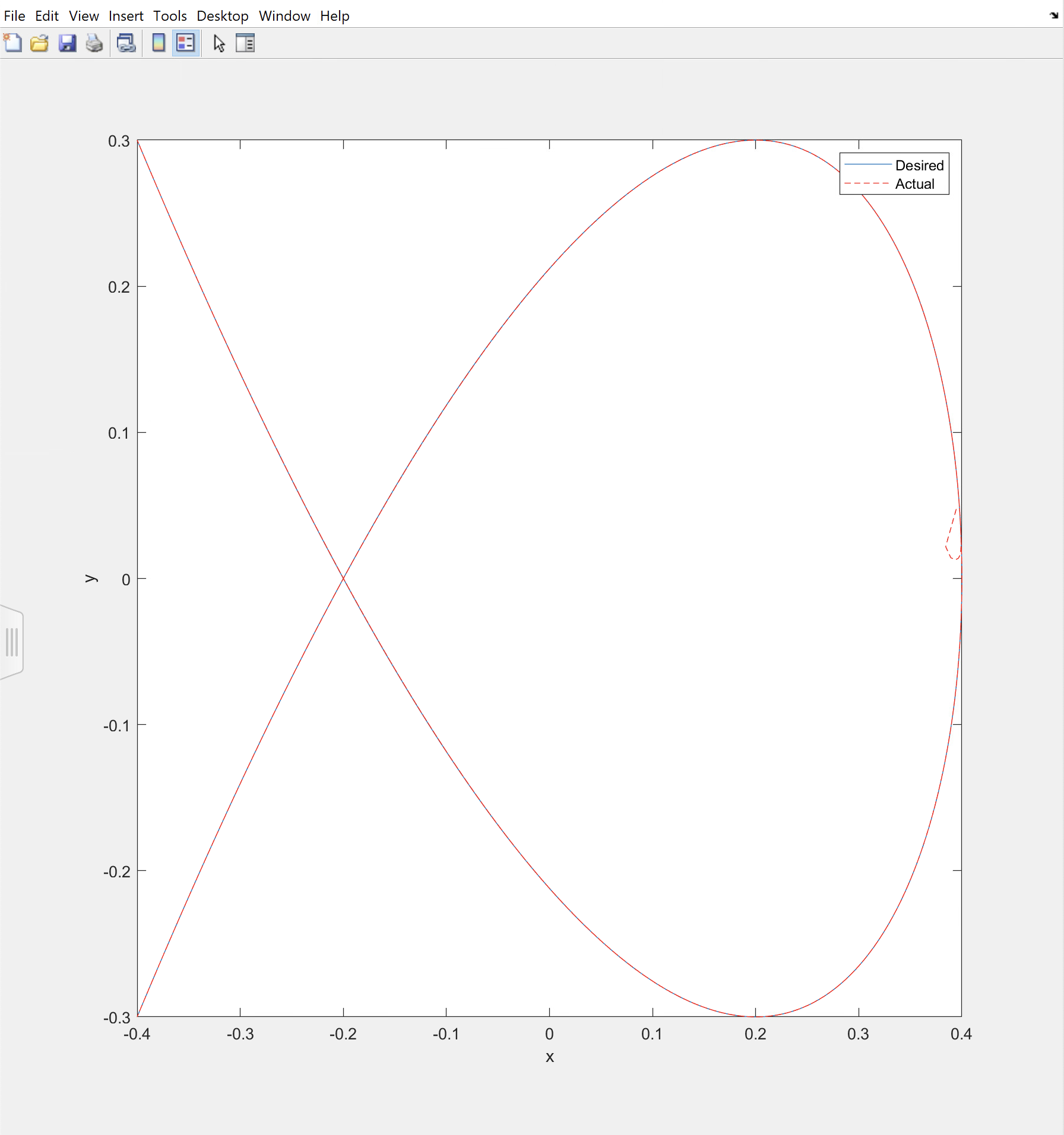
we were tasked to create a robot in Matlab and create a path for the end effector to follow. The first image shows the robot that has 6 degrees of freedom. The second image shows the desired (programmed) and actual path. The final code for the project can be seen here
T-shirt shooter
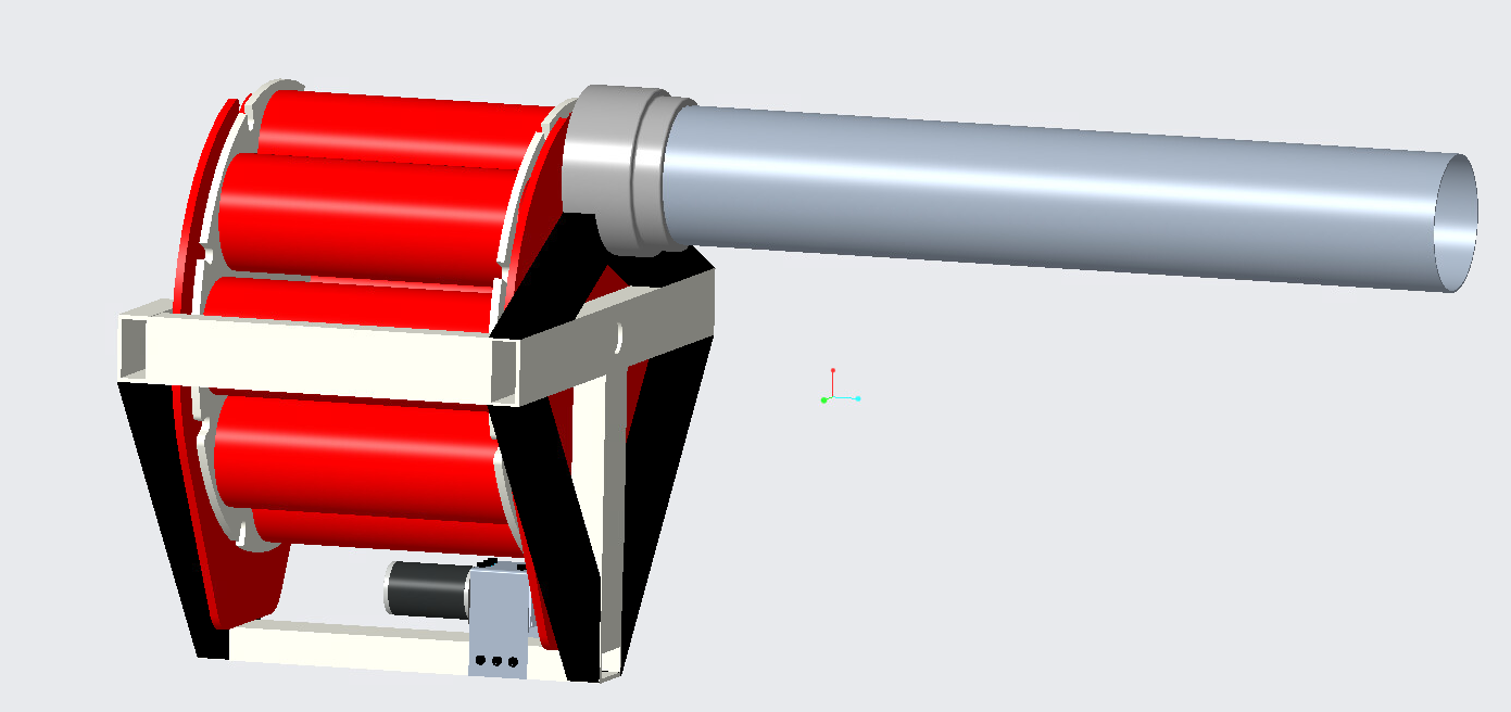
In my CAD class, we had a project to design something with a minimum of 9 unique parts using Creo Parametric. I decided to design a gatling t-shirt shooter. The project also required that we ran a finite element analysis on two parts in the assembly. This project allowed me to use my knowledge of Creo Parametric and Simulate. To see the full assembly, check out my GrabCAD.
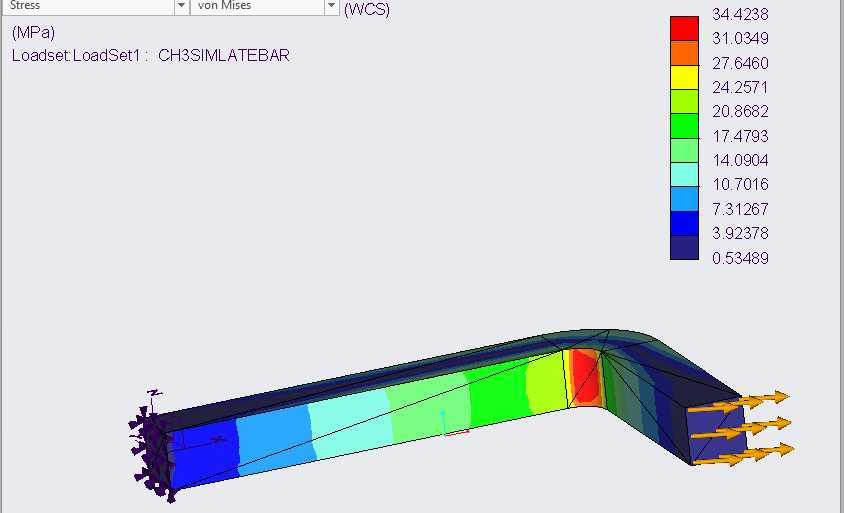
Finite Element Analysis on an L-shaped bar with an applied force
I am currently taking a class where we are learning finite element analysis. I used Creo paramatric to create an L-shaped bar. After creating the part, it was imported into Creo Simulate. In the Creo Simulate, a displacement constraint was added to one end of the bar and a load to the other end. This can be seen in the picture down below. I really liked this assingment because I would like to go into design after graduation.
Punch Force Analysis
I was a part of a three person team that designed and executed an experiment using a load cell. In addition to the load cell, a data acquisition hardware and LabVIEW were used. Labview was used to record data which was then exported to Excel for analysis. In order to properly record the force of a punch, a mechanism needed to be designed to mount the load cell. Various test subjects punched the jig. Figure 1 illustrates the punching device. Figure 2 shows a test subject ready to punch the device.
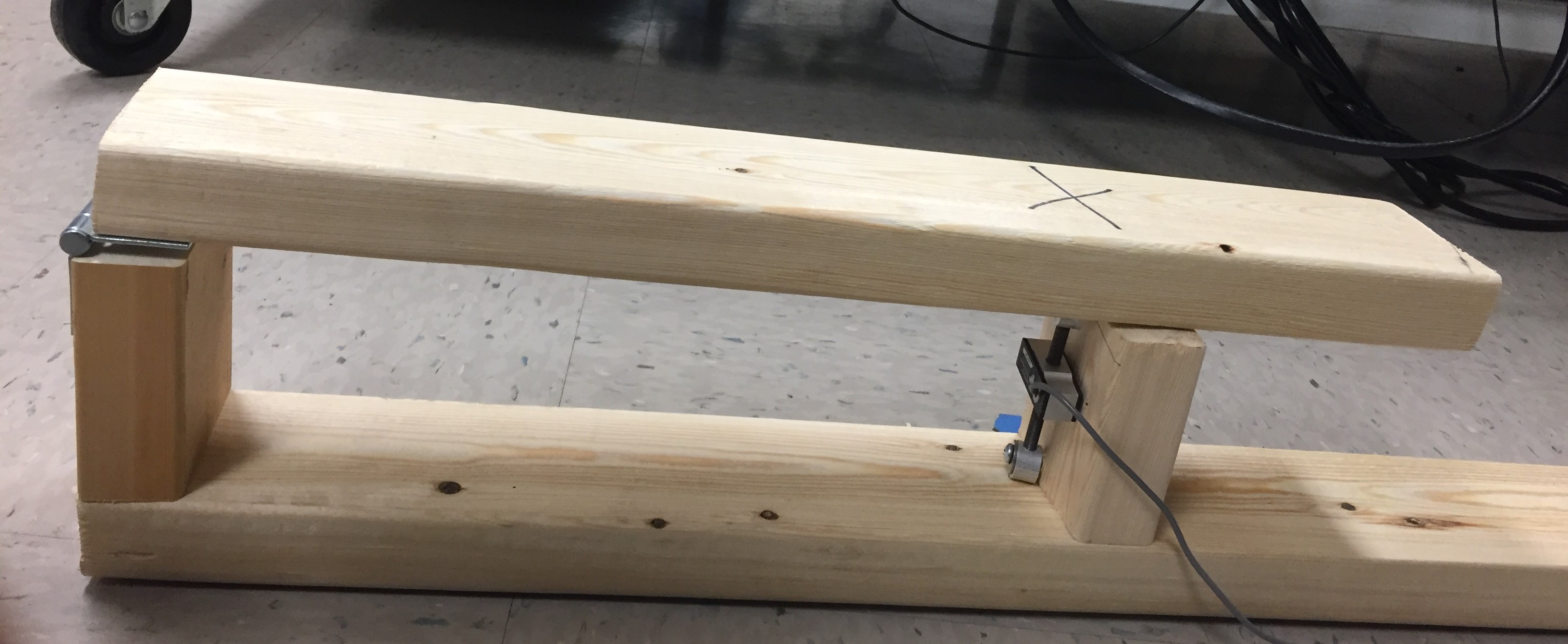
Figure 1: Punching Mechanism
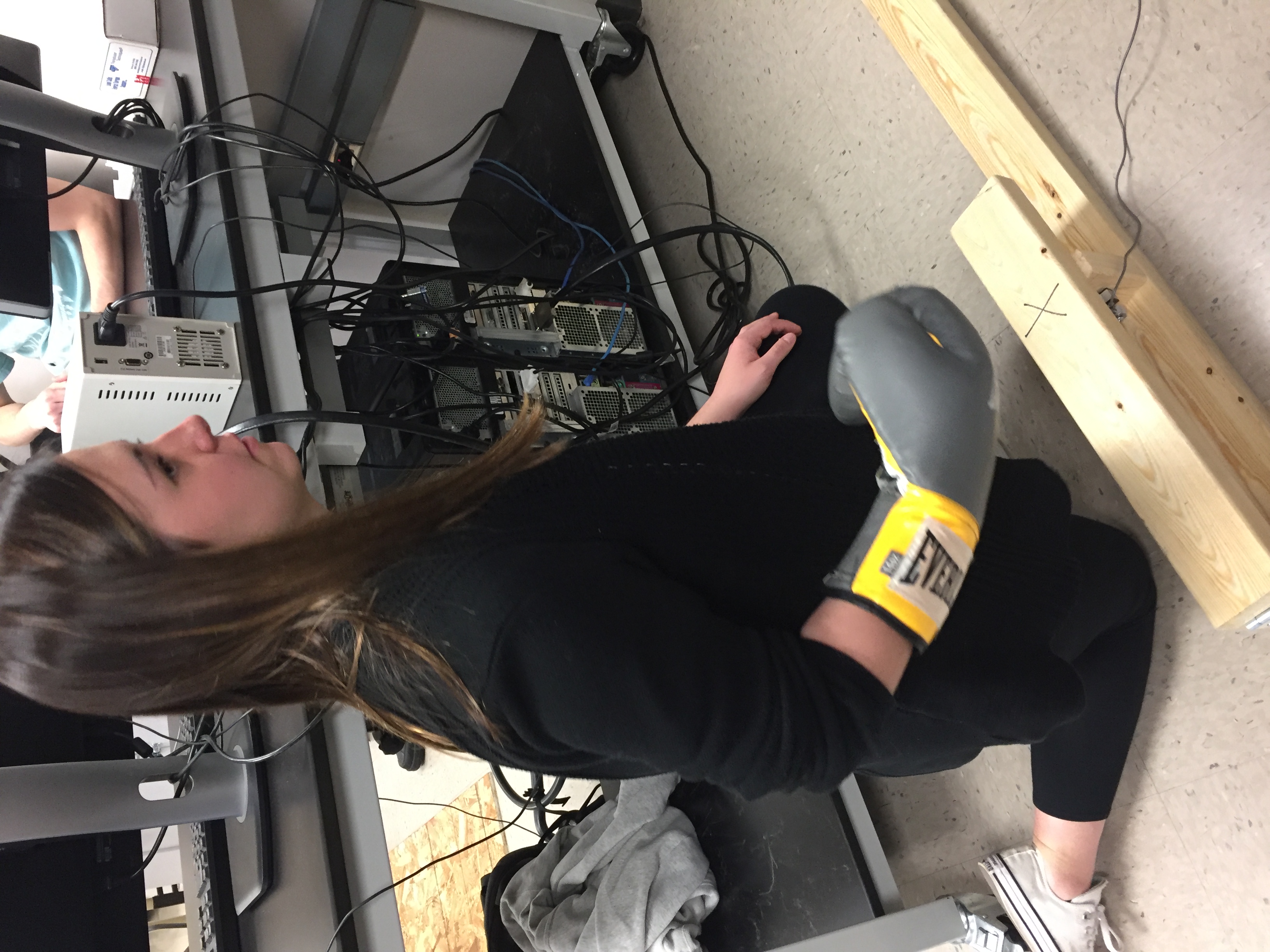
Figure 2: Test subject ready to punch
The data that came directly from Labview couldnt be neccessarily analyzed. The data that was output from Labview included voltages and times. Essentially, whenever the load cell experience some amount of force, it would output a voltage. Before the experiment, our team worked on creating a calibration curve that essentially converted voltages into force (N). One of the graphs that was analyzed can be seen in Figure 3. On the graph, it can be seen around 6 seconds that the load cell experienced around 1500 N. The other spikes in force after 6 seconds are most likely due to the bounce of the mechanism.
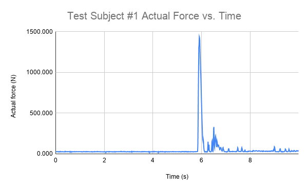
Figure 3: Graph of Force vs Time
This experiment was done for my Mechanical Engineering 303: Instrumentation and Measurements. This is hands down one of my top 3 favorite classes I have taken in college. The full lab report can be seen here.
Saturn V Stage Seperation Model: Matlab
As a class assingment, I was tasked to create a Saturn V launch model. Part of the code can be seem down below. This model kept track of stage seperation, rocket mass, and amount of fuel. The full code can be found here.
clear; clc;

%Declaring Variables
RadiusOfEarth=6.38*10^6; %radius of the Earth (m)
MassOfEarth=5.98*10^24; %mass of the Earth (kg)
gravity=6.673*10^-11; %gravitational constant (N*m^2/kg^2)

Stage1Thrust=34*10^6; %Thrust of stage 1 (N)
Stage2Thrust=5*10^6; %Thrust of stage 2 (N)
Stage3Thrust=1*10^6; %Thrust of stage 3 (N)

Stage1Velocity=2580; %exhaust velocity of stage 1 (m/s)
Stage2Velocity=4130; %exhaust velocity of stage 2 (m/s)
Stage3Velocity=4130; %exhaust velocity of stage 3 (m/s)

Stage1EmptyMass=131000; %empty mass of stage 1 (kg)
Stage2EmptyMass=36000; %empty mass of stage 2 (kg)
Stage3EmptyMass=11000; %empty mass of stage 3 (kg)

Stage1FueledMass=2300000; %full mass of stage 1 (kg)
Stage2FueledMass=480000; %full mass of stage 2 (kg)
Stage3FueledMass=119000; %full mass of stage 3 (kg)
PayloadMass=52000; %mass of the payload (kg)

dt=.1; %step size
n=10000; %number of iterations
i=2;


time=zeros(1,n); %time array
RocketMass=zeros(1,n); %mass array
yPosition=zeros(1,n); %position array
velocity=zeros(1,n); %velocity array
acceleration=zeros(1,n); %acceleration array

%starting values
time(1)=0; %starting value for time
yPosition(1)=0; %starting value for position
velocity(1)=0; %starting value for velocity
acceleration(1)=-gravity*MassOfEarth/(RadiusOfEarth+yPosition(1))^2; %starting value for acceleration
RocketMass(1)=Stage1FueledMass+Stage2FueledMass+Stage3FueledMass+PayloadMass; %starting value for mass

MRBJ1=Stage1EmptyMass+Stage2FueledMass+Stage3FueledMass+PayloadMass; %mass after stage 1
MRBJ2=Stage2EmptyMass+Stage3FueledMass+PayloadMass; %mass after stage 2
MRBJ3=Stage3EmptyMass+PayloadMass; %mass after stage 3

%the rest of the code can be seen in the link provided above in the description